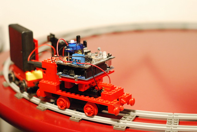
We travelled to Makerfaire Detroit as part of our marketing push for the Diyode CodeShield crowdfunding campaign. It seemed like a great excuse to play with some Lego. Not that I really need an excuse.
This year I dusted off some vintage train parts (Set #7722, for those playing along at home). The train is motorized, and pulls it’s own battery pack around the track.
Wouldn’t it be fun if it stopped at stations on it’s own? Let’s add an Arduino and a CodeShield and see if we can make Lego even more interactive.
If we want to control our train with a CodeShield, the first thing we need to be able to do is to turn the motor on and off. Fortunately the CodeShield comes equipped with a relay and terminal block for just such an emergency.
Using a relay
A relay is essentially an electronically controlled switch. All we need to do is send it a HIGH or LOW value, and it will turn on or off.
If you look closely at the terminal block on the CodeShield, you’ll see that the pins are labelled ‘NC’, ‘C’, and ‘NO’. These translate from engineer speak as ‘Normally Closed’, ‘Common’ and ‘Normally Open’. This means that when the relay is turned off, the ‘NC’ and ‘C’ pins are connected. When the relay is turned on, the ‘C’ and ‘NO’ pins are connected.
This gives us a basic on/off switch. All we have to do is wire this switch — our relay — in between the battery and the motor.
Given that my version of this set is thirty years old, the cables are long since gone. I’ve modified this circuit just a little to use a single battery pack for both the Arduino and the train motor.
The beginnings of a sketch
#define ENCODER_A 14
#define ENCODER_B 15
#define ENCODER_PORT PINC
#define SWITCH 13
#define BUTTON 12
#define RGB_RED 11
#define RGB_GREEN 10
#define RGB_BLUE 9
#define LED 6
#define SERVO 5
#define PIEZO 3
#define RELAY 2
#define POT 2
#define HALL 3
#define THERMISTOR 4
#define PHOTOCELL 5

void start_driving() {
  // Turn on the relay.
  digitalWrite(RELAY,HIGH);
}

void stop_driving() {
  // Turn off the relay.
  digitalWrite(RELAY,LOW);
}

void keep_driving() {
  // Do nothing for a short time.
  delay(10);
}

void setup() {
  // Make sure we can turn our relay on.
  pinMode(RELAY, OUTPUT);
  start_driving();
}

void loop() {
  keep_driving();
}
Driving blind
If we want to stop at a given station, we might be able to do it with some careful timing. I timed how long it takes the train to run this track, and averaged five laps. This sketch will run the train for that amount of time, and then stop and wait for a moment.
#define ENCODER_A 14
#define ENCODER_B 15
#define ENCODER_PORT PINC
#define SWITCH 13
#define BUTTON 12
#define RGB_RED 11
#define RGB_GREEN 10
#define RGB_BLUE 9
#define LED 6
#define SERVO 5
#define PIEZO 3
#define RELAY 2
#define POT 2
#define HALL 3
#define THERMISTOR 4
#define PHOTOCELL 5

void start_driving() {
  // Turn on the relay.
  digitalWrite(RELAY,HIGH);
}

void stop_driving() {
  // Turn off the relay.
  digitalWrite(RELAY,LOW);
}

void keep_driving(int time) {
  // Do nothing for a short time.
  delay(time);
}

void setup() {
  // Make sure we can turn our relay on.
  pinMode(RELAY, OUTPUT);
}

void loop() {
  // Drive forwards for 8.1 seconds.
  // I got that number by timing the train
  // with a stopwatch.
  start_driving();
  keep_driving(8100);
  stop_driving();

  // Stay put for a second.
  delay(1000);
}
Sorry for the noise. I did mention this set is from 1985, right? Big coarse metal gears instead of fine toothed nylon gears. You should have heard it before WD-40.
Not only does our train not stop at our station, it doesn’t even stop at the same place each time. We could trim this program to be a little more accurate, but it will never be completely, 100% true. As the batteries wear down, our train will move slower and our timing will be off again.
This is the robot equivalent of walking forwards blindfolded. This works just fine for some simple cases, but one wrong move and you’ll never figure figure out where you are. This is called ‘Open Loop Control’.
Watching for the station
So we can’t rely on just timing to make sure our train always gets to the station. We need to be able to tell when the train reaches the station, and turn the engine off.
The CodeShield has quite a few sensors and switches on it. For this example, we’ll use lego magnets, like the one one this post:
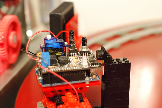
These are out of some old M-Tron sets. The CodeShield has an on-board Hall Effect sensor which can measure magnetic fields.
This strategy is called ‘Closed Loop Control’ — instead of blindly stepping forwards, our train will keep looking for the station, and stop when we see it.
Using a Hall effect sensor
The Hall effect sensor we’ve used on the codeshield is an analog sensor. Digital sensors return a true or false value. Analog sensors return pretty much any number, and we need to be able to interpret that number in software. On the Arduino, that number can vary between 0 and 1023, which is quite a range. For our purposes, we need to know if a magnet is present.
Let’s not break out the textbooks just yet. Instead, we’ll measure how strong our little lego magnets are.
To do this, we’ll use a custom sketch that will show us exactly what the Arduino sees when we bring our magnet near.
#define ENCODER_A 14
#define ENCODER_B 15
#define ENCODER_PORT PINC
#define SWITCH 13
#define BUTTON 12
#define RGB_RED 11
#define RGB_GREEN 10
#define RGB_BLUE 9
#define LED 6
#define SERVO 5
#define PIEZO 3
#define RELAY 2
#define POT 2
#define HALL 3
#define THERMISTOR 4
#define PHOTOCELL 5

void setup() {
  // Initialize serial communications at 9600 bps:
  Serial.begin(9600);
}

void loop() {
  // Measure the hall effect sensor.
  int hall = analogRead(HALL);

  // Print the results to the serial monitor.
  Serial.print("hall sensor = ");
  Serial.println(hall);

  // Wait a little bit before the next measurement

  delay(100);
}
Once you’ve got this sketch loaded and running, click the Serial Monitor icon at the top right of the Arduino IDE. Here are the numbers I got when I tried it:
hall sensor = 520
hall sensor = 519
hall sensor = 519
hall sensor = 517
hall sensor = 512
hall sensor = 502
hall sensor = 500
hall sensor = 501
hall sensor = 499
hall sensor = 499
hall sensor = 499
hall sensor = 499
hall sensor = 499
hall sensor = 499
hall sensor = 499
hall sensor = 500
hall sensor = 502
hall sensor = 508
hall sensor = 516
hall sensor = 519
hall sensor = 520
After a little bit of experimentation, we can see that the average measurement on our Hall sensor is about 519. When we put our magnet near it, it can vary down to about 500. If I flipped the magnet over, it’d go about the same amount the other way. So let’s call that about 540. Just to be safe, let’s assume a magnet is present if the reading from the hall effect sensor varies by more than 10.
Let’s build a function that tells us if a our sensor sees a magnet:
#define ENCODER_A 14
#define ENCODER_B 15
#define ENCODER_PORT PINC
#define SWITCH 13
#define BUTTON 12
#define RGB_RED 11
#define RGB_GREEN 10
#define RGB_BLUE 9
#define LED 6
#define SERVO 5
#define PIEZO 3
#define RELAY 2
#define POT 2
#define HALL 3
#define THERMISTOR 4
#define PHOTOCELL 5

// Take some measurements
const int hall_normal = 519;
const int hall_sensitivity = 10;

boolean magnet_present() {
  // Take a reading.
  int hall_reading = analogRead(HALL);

  // Test to see if the reading is further away from normal
  // then our sensitivity value.  If it is, return true.
  // otherwise return false.
  return(abs(hall_reading - hall_normal) > hall_sensitivity);
}

void setup() {
  // Initialize serial communications at 9600 bps:
  Serial.begin(9600);
}

void loop() {
  if( magnet_present() ) {
    Serial.println("I see a magnet!");
  } else {
    Serial.println("I don't see a magnet!");
  }

  // Wait a little bit before the next measurement
  delay(100);
}
And here’s the result:
I don't see a magnet!
I don't see a magnet!
I don't see a magnet!
I don't see a magnet!
I see a magnet!
I see a magnet!
I see a magnet!
I see a magnet!
I see a magnet!
I see a magnet!
I see a magnet!
I see a magnet!
I see a magnet!
I see a magnet!
I see a magnet!
I don't see a magnet!
I don't see a magnet!
I don't see a magnet!
Instead of a number, now we have a yes-or-no answer.
Loops
So now we can measure our magnet. That’s a good thing! We’re almost done! We just need to figure out what our train should do when it sees our magnet. This means we have to build the loop in our closed loop control system.
A while loop is just the thing. It will keep repeating all of the instructions within it’s curly brackets, as long as it’s condition is true. In this case, we want it to keep looping as long as we don’t see the magnet. The ‘!’ in our condition reverses is — basically it says “Not!”.
Here’s the loop:
void loop() {
  // Start Driving.
  start_driving();

  // If we can't see a magnet, keep driving.
  while(!magnet_present()) {
    keep_driving();
  }

  // If we're out of the loop, we must have seen a magnet.
  stop_driving();

  // Wait a little bit before starting again.
  delay(1000);
}
And here’s the whole program:
#define ENCODER_A 14
#define ENCODER_B 15
#define ENCODER_PORT PINC
#define SWITCH 13
#define BUTTON 12
#define RGB_RED 11
#define RGB_GREEN 10
#define RGB_BLUE 9
#define LED 6
#define SERVO 5
#define PIEZO 3
#define RELAY 2
#define POT 2
#define HALL 3
#define THERMISTOR 4
#define PHOTOCELL 5

// Take some measurements
const int hall_normal = 519;
const int hall_sensitivity = 10;

boolean magnet_present() {
  // Take a reading.
  int hall_reading = analogRead(HALL);

  // Test to see if the reading is further away from normal
  // then our sensitivity value.  If it is, return true.
  // otherwise return false.
  return(abs(hall_reading - hall_normal) > hall_sensitivity);
}

void start_driving() {
  // Turn on the relay.
  digitalWrite(RELAY,HIGH);
}

void stop_driving() {
  // Turn off the relay.
  digitalWrite(RELAY,LOW);
}

void keep_driving() {
  // Do nothing for a short time.
  delay(10);
}

void setup() {
  // Make sure we can turn our relay on.
  pinMode(RELAY, OUTPUT);
}

void loop() {
  // Start Driving.
  start_driving();

  // If we can't see a magnet, keep driving.
  while(!magnet_present()) {
    keep_driving();
  }

  // If we're out of the loop, we must have seen a magnet.
  stop_driving();

  // Wait a little bit before starting again.
  delay(1000);
}
All the bells and whistles!
Our train works! It starts and stops! But we can do a little better. Here’s the final sketch that we used at MakerFaire Detroit, with some additional refinements.
#define ENCODER_A 14
#define ENCODER_B 15
#define ENCODER_PORT PINC
#define SWITCH 13
#define BUTTON 12
#define RGB_RED 11
#define RGB_GREEN 10
#define RGB_BLUE 9
#define LED 6
#define SERVO 5
#define PIEZO 3
#define RELAY 2
#define POT 2
#define HALL 3
#define THERMISTOR 4
#define PHOTOCELL 5

// Take some measurements
const int hall_normal = 519;
const int hall_sensitivity = 10;

boolean magnet_present() {
  // Take a reading.
  int hall_reading = analogRead(HALL);

  // Test to see if the reading is further away from normal
  // then our sensitivity value.  If it is, return true.
  // otherwise return false.
  return(abs(hall_reading - hall_normal) > hall_sensitivity);
}

void start_driving() {
  // Turn on the relay.
  digitalWrite(RELAY,HIGH);

  // Turn on the RGB LED.
  digitalWrite(RGB_GREEN, HIGH);
}

void stop_driving() {
  // Turn off the relay.
  digitalWrite(RELAY,LOW);

  // Turn off the RGB LED.
  digitalWrite(RGB_GREEN, LOW);
}

void keep_driving() {
  // Do nothing for a short time.
  delay(10);
}

void chirp() {
  for( int i = 0; i < 5; i++ ) {
    tone(PIEZO, 1000, 10);
    delay( 90 );
  }
}

void countdown() {
  for( int i = 0; i < 5; i++ ) {
    digitalWrite( RGB_RED, HIGH );
    delay( 100 );
    digitalWrite( RGB_RED, LOW );
    delay( 900 );
  }
}

void setup() {
  // Make sure we can turn our relay on.
  pinMode(RELAY, OUTPUT);

  // Set up the RGB LED.
  pinMode( RGB_RED, OUTPUT );
  pinMode( RGB_GREEN, OUTPUT );
  pinMode( RGB_BLUE, OUTPUT );

  // Also, set up the piezo.
  pinMode(PIEZO, OUTPUT);
}

void loop() {
  // Start Driving.
  chirp();
  start_driving();

  // If we can't see a magnet, keep driving.
  while(!magnet_present()) {
    keep_driving();
  }

  // If we're out of the loop, we must have seen a magnet.
  stop_driving();
  chirp();

  // Wait a little bit before starting again.
  countdown();
}
The next project
Control loops are the foundation of many types of software. In fact, most of my Arduino projects have been based around a single control loop just like this one — watch for a sensor to change, and then do something when it does.
The CodeShield has many different sensors, and many different outputs. Next time, we’ll follow up with a laser tripwire that uses a very similar kind of loop.