CodeShield Soldering Instructions
Follow these instructions if your board is marked “Version 1.2” and is blank on the underside.
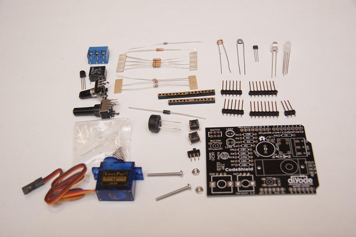
Required Tools
To assemble the CodeShield you will need a soldering iron, solder, side cutters, wire strippers, and a small phillips head screwdriver.
Order of installation
If you install the components in this order it will make the solding job easier.
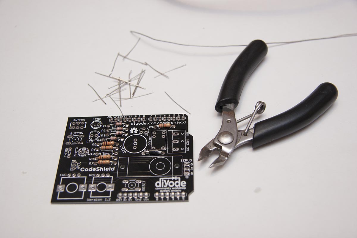
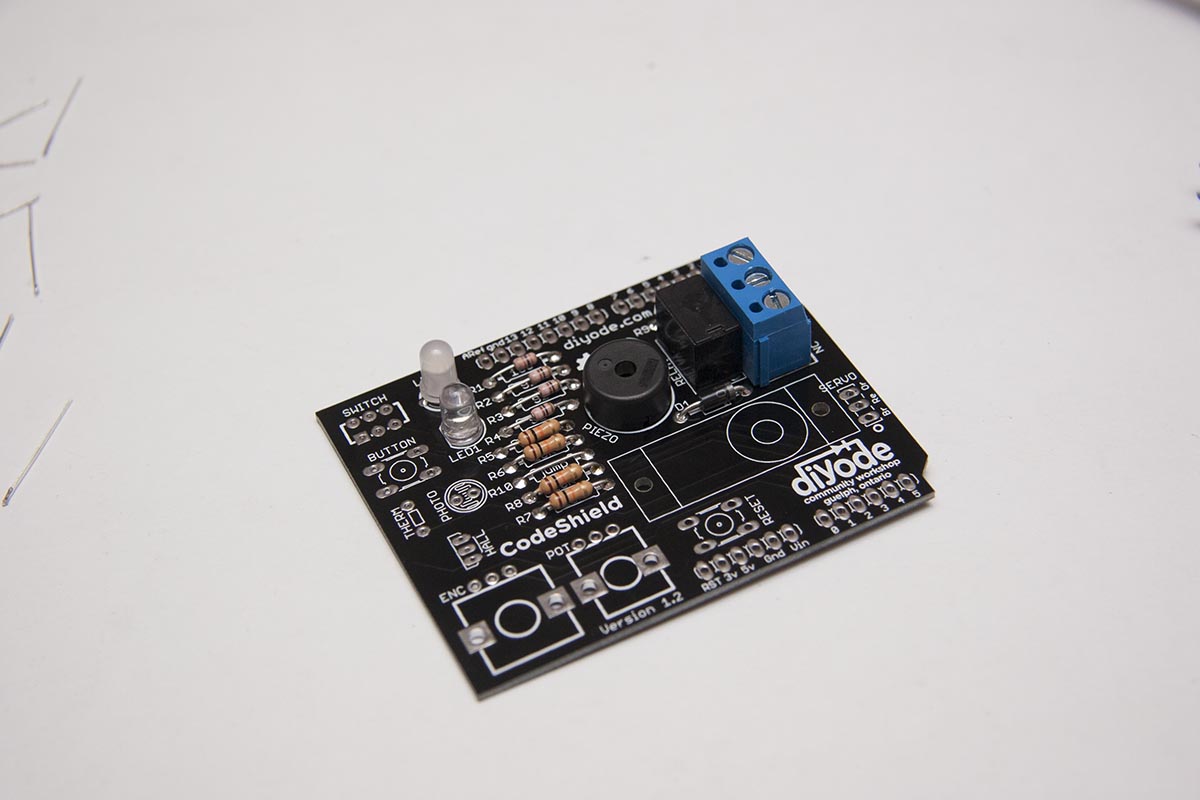
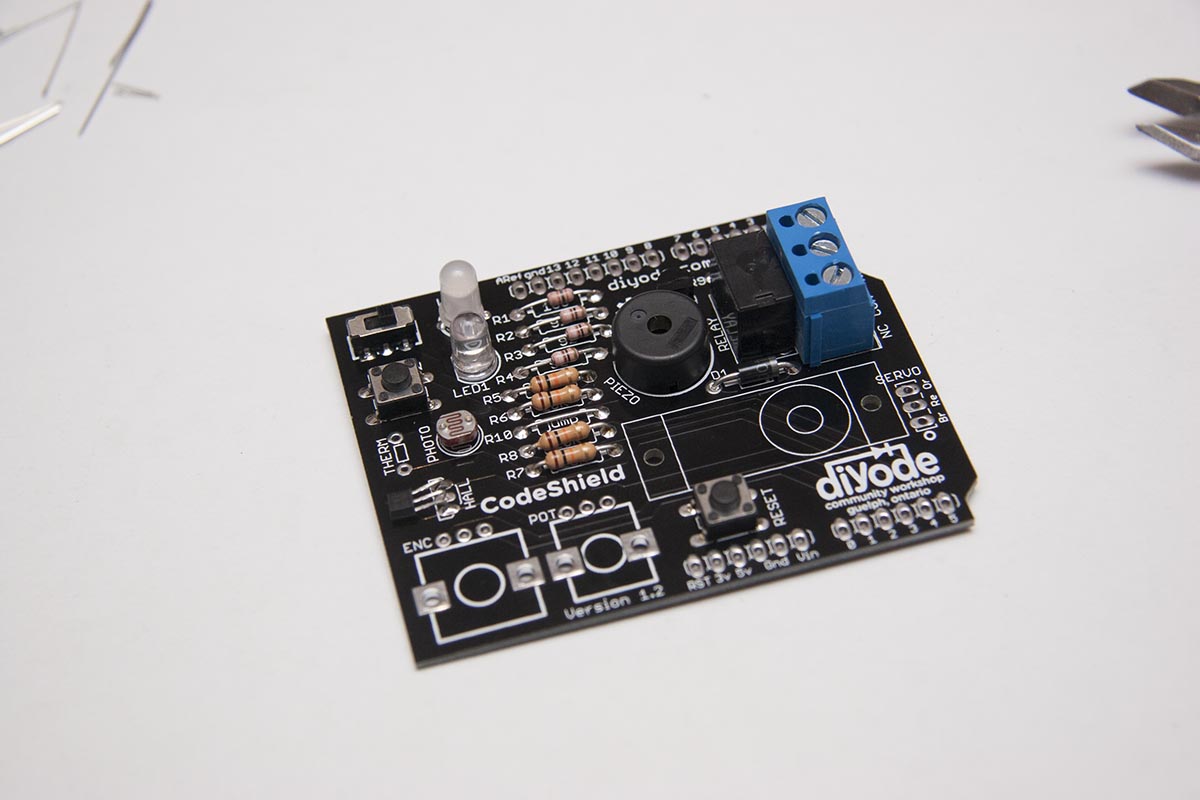
1) Resistors
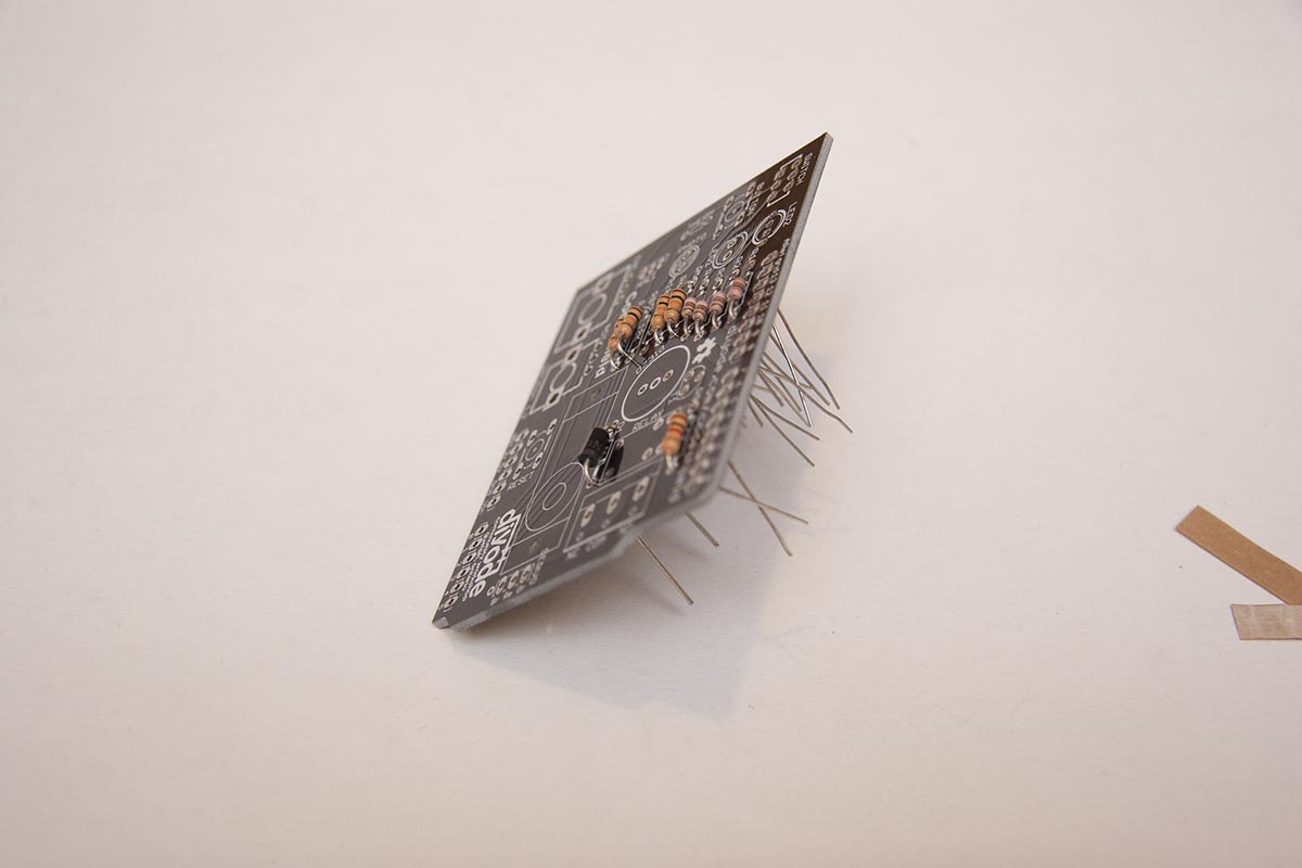
First bend and place all the resistors. You can solder them one at a time as you place them; or the quicker method is place them all then solder them. Use the side cutters to clip all the leads.
- R1 – 100 ohm Br-Bl-Br
- R2 – 92 ohm Wt-Br-Bl
- R3 – 92 ohm Wt-Br-Bl
- R4 – 92 ohm Wt-Br-Bl
- R5 – 10K ohm Br-Bl-Or
- R6 – 10K ohm Br-Bl-Or
- R7 – 10K ohm Br-Bl-Or
- R8 – 10K ohm Br-Bl-Or
- R9 – 1K ohm Br-Bl-Rd
- R10 – Jumper (Step 3)
2) Diode

Unlike the resistors, it is important that the diode go in the right way round. Bend the leads, and insert into the board with the silver stripe on the diode aligned with the stripe on the diode picture on the board. Then solder. When you clip the leads save one of them to use as a jumper in the next step.
3) Jumper
The volume of the piezo is determined by the value of R10. For most uses, we want the piezo to sound at full volume, so R10 is just a wire jumper. For this, we use part of the discarded wire that was clipped off the diode after installation. Bend one side of the clipped diode lead to make a tail that is about twice the thickness of the circuit board. Then line up the bend in the hole in order to make the second bend. Solder and clip the excess lead.
To make the piezo quieter for classroom use, find an appropriate value for your situation. To disable the piezo altogether, leave R10 off completely.
4) Piezo
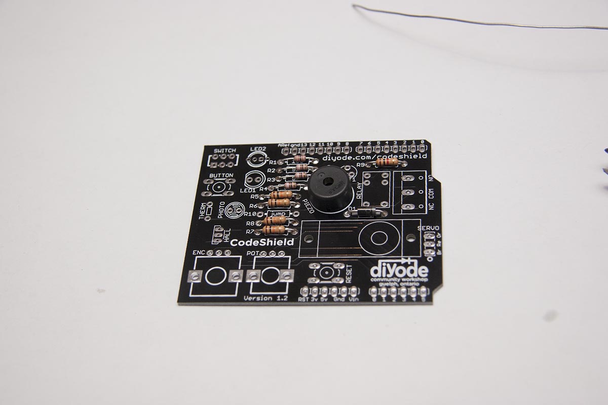
Mount flush to the board and solder.
5) Relay
Insert the relay and rest the board on it upside down while you solder the first pin. Check the relay is flush to the board and solder the remaining pins.
6) Terminal Block

Insert with the connector holes facing out, and rest the board upside-down to keep the block in place. This may take a good bit of heat to wick the solder onto the pins.
7) LED – 2 lead
Match the flat side of the LED base with the image on the board, flush with the board. Try to avoid lingering too long with the soldering iron, as the heat can damage the LED.
8) RGB LED – 4 lead
Match up the longest lead with the square solder pad on the board. Push it forcefully into the board to get it as close to the board as you can. Solder all four leads, and clip.
9) Transistor

Bend the middle leg forward and then down to mount it closer to the board.
10) Switch, Reset button & Button
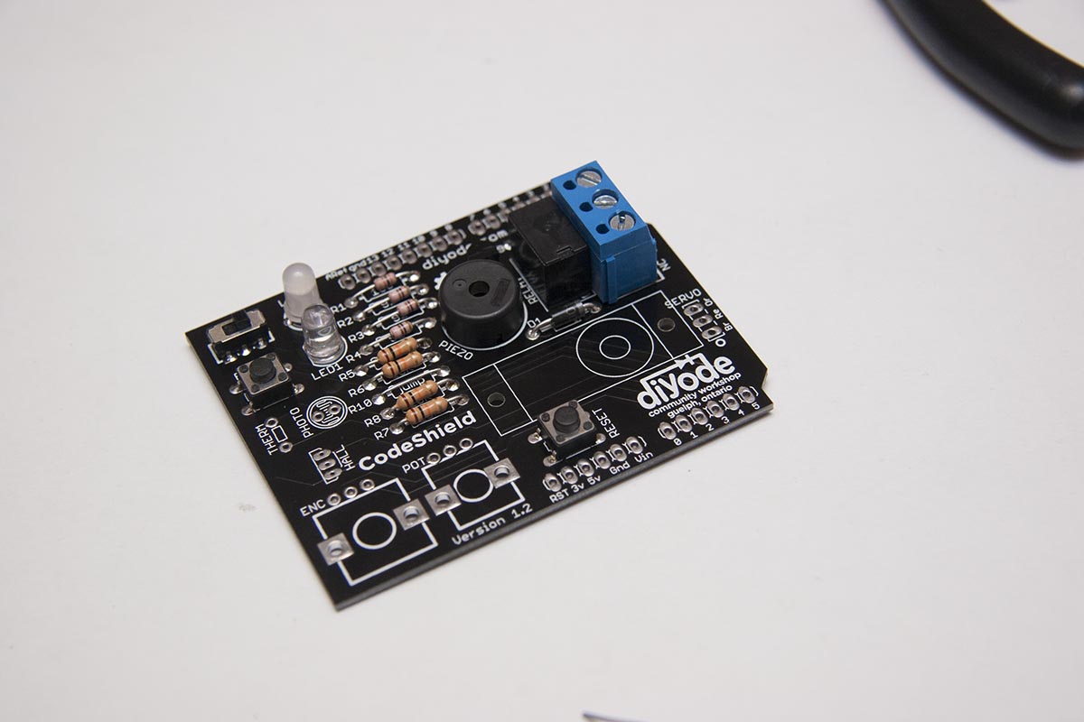
Press forcefully into the to the board until flush. Solder.
11) PhotoCell
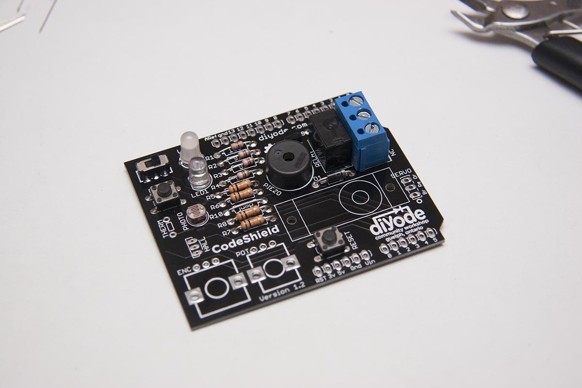
Mount flush with the board, or as close as it will fit. Use as little heat as possible.
12) Hall Effect Sensor
Once soldered this will be pushed down so it lies flat with the board. Leave enough height to do that.
13) Pot & Encoder
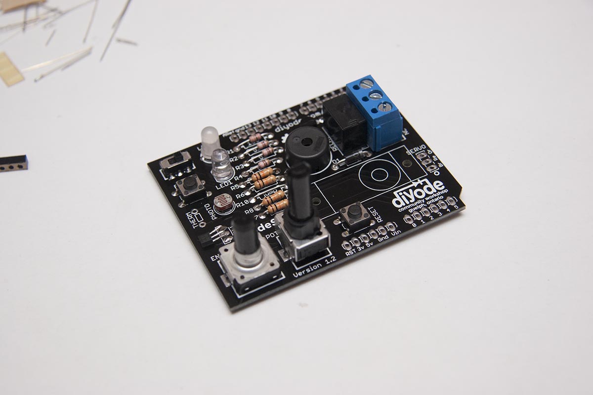
These can be tricky to get into the board, as the fit is quite tight. Insert the three signal pins first, then rock the component back and forth until it pops through. Solder the feet first, then the connectors
14) Thermistor
Leave it poking up from the board about 3/4″, so that it can be grasped between finger and thumb to measure body heat. Solder and clip.
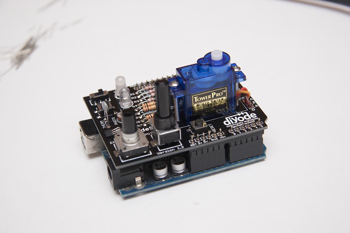
15) Servo
There are two ways to attach the servo. 1) You can attach it with a very short lead, solder directly to the board. This is the cleanest and most robust way to go, and is recommended for classroom or multi-user settings. 2) You can also use the three pin header to connect the servo using the entire lead wire. This is easier and useful if you may want to use the servo mounted elsewhere.
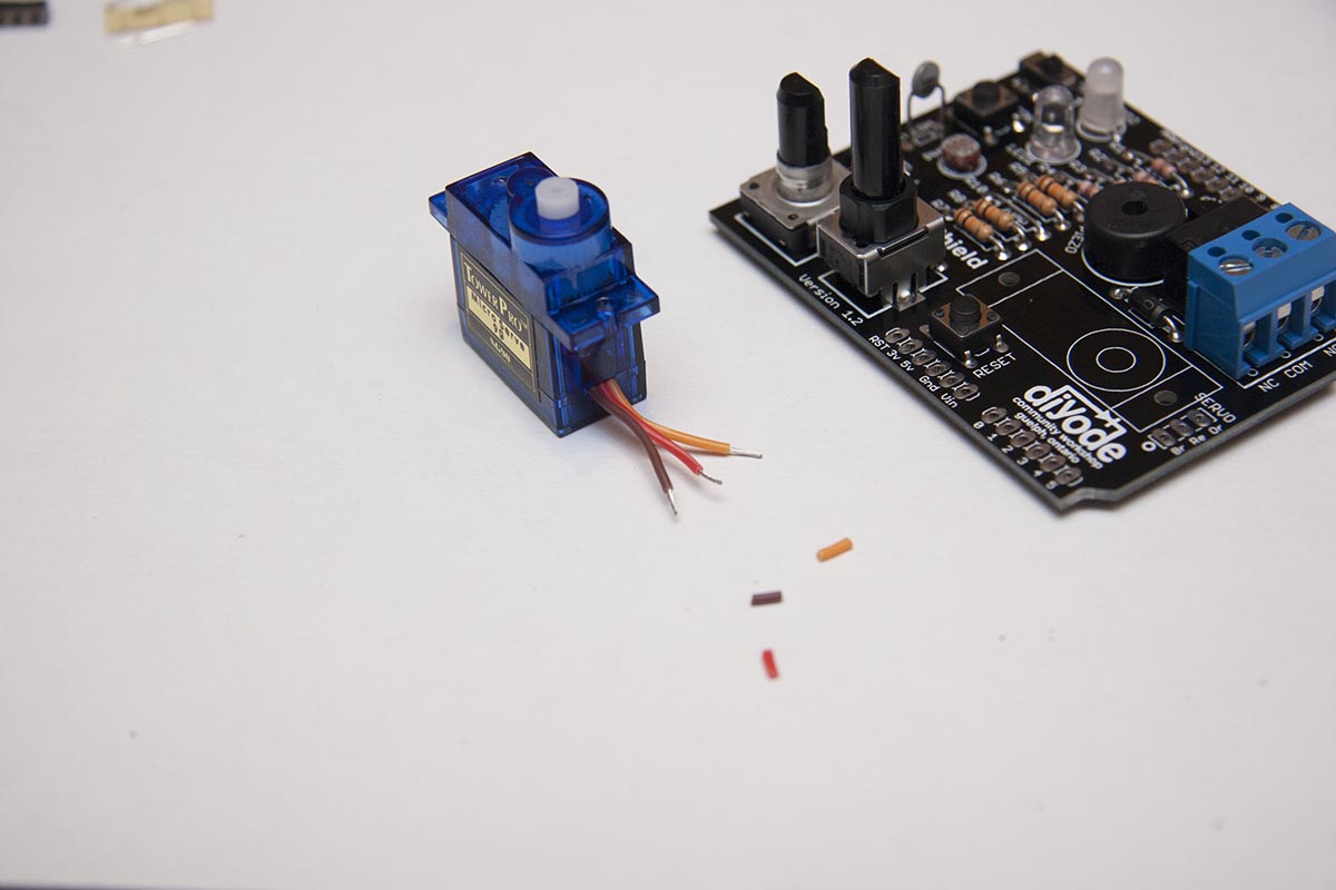
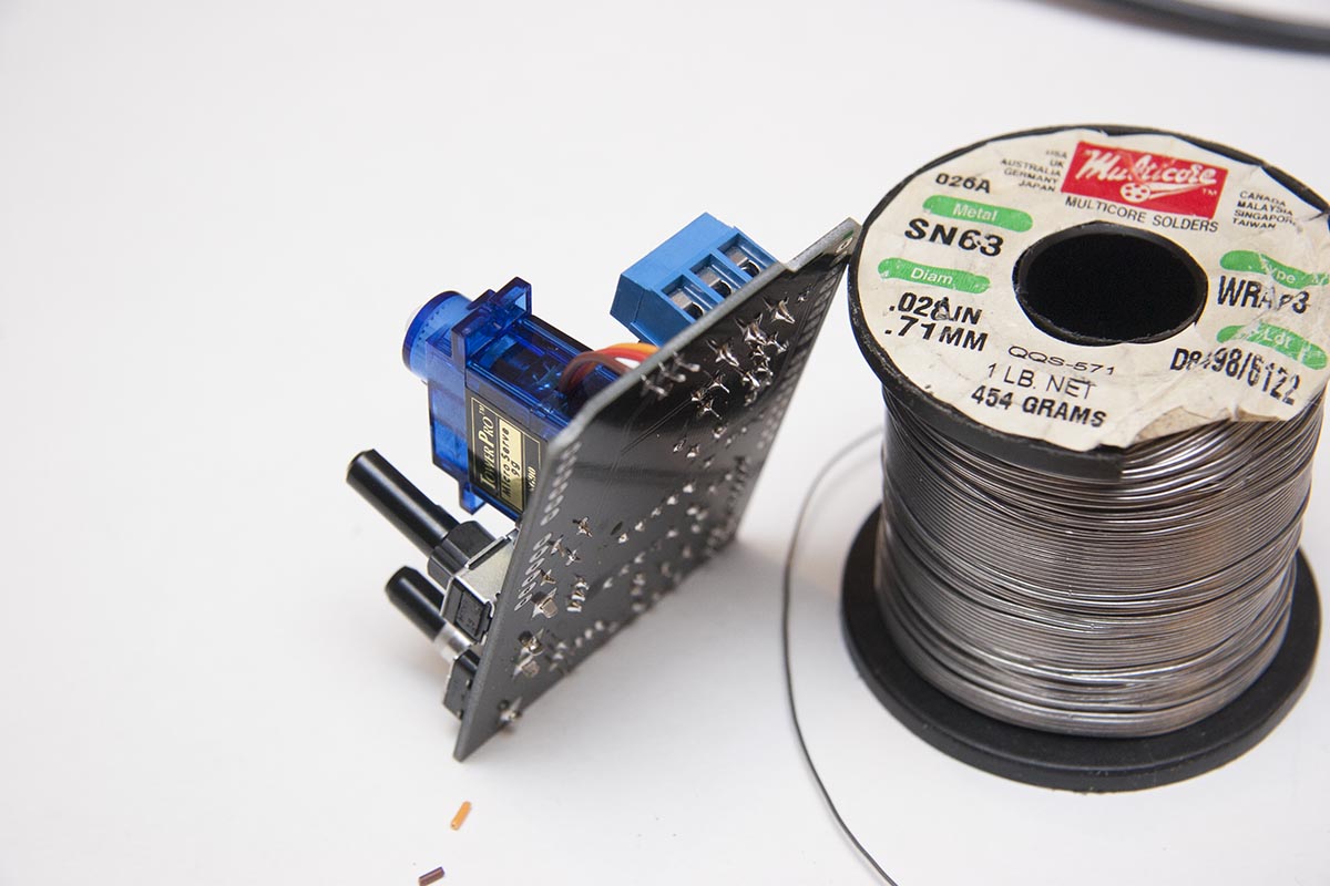
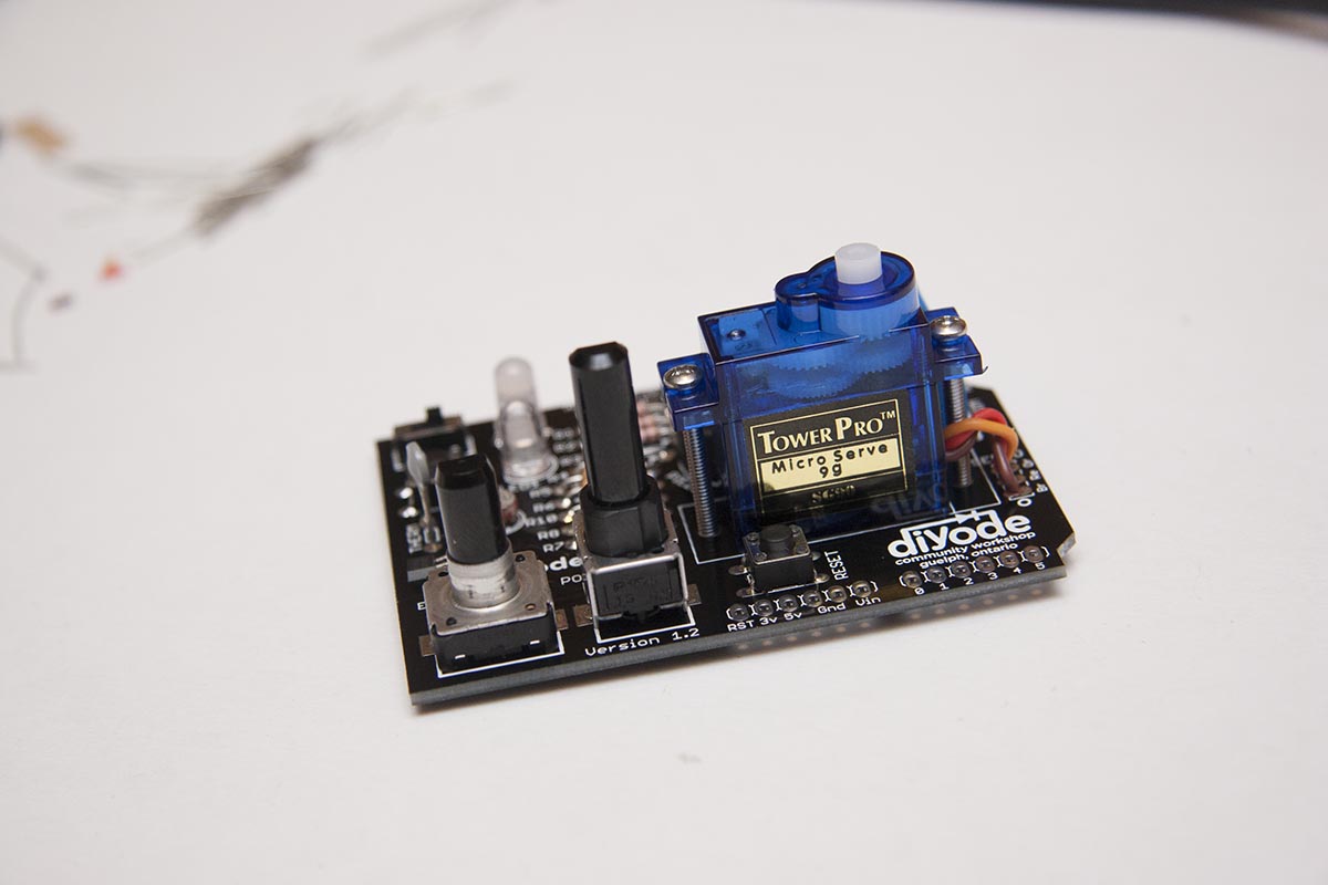
1) Cut the wire at about 1.5″, strip off about 1/8″, twist and tine the leads. Insert the tinned leads into the board and solder. The order of the leads going into the board is the same as they come out of the servo (IE, orange furthest away from the diyode logo, then red then black) Abbreviations of the colour is marked on the boards next to the holes. Attach the servo to the board with the bolts and nuts.

2) Insert the three pin header into the board with the leads pointing up. Solder from the underside. Plug the servo lead into the header pins and bolt the servo to the board.
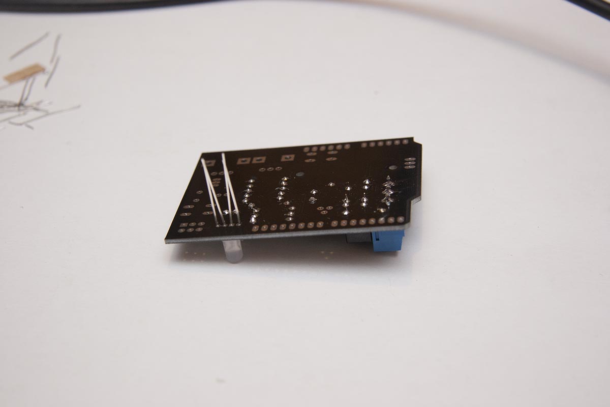
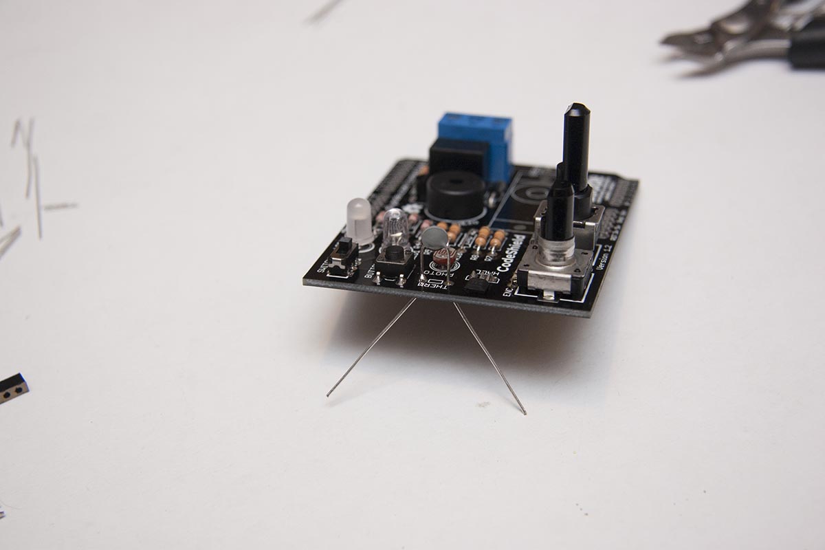
16) Headers
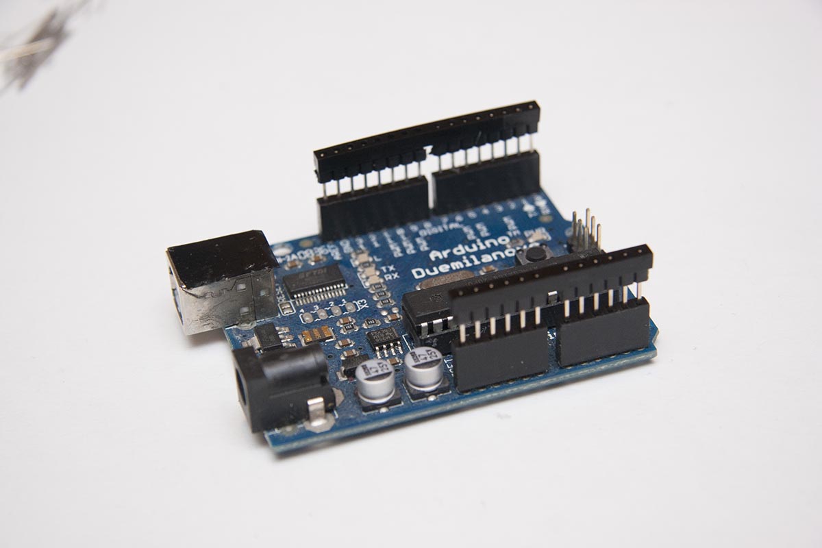
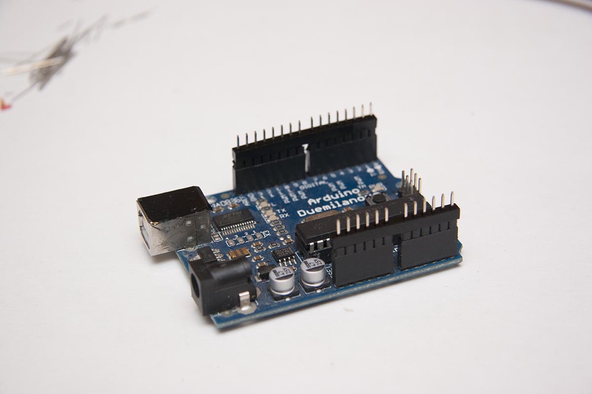
Peel any paper off the acrylic stand-offs. Push the long side of the headers into the arduino, and put the stand-offs on them above the plastic shroud of the header pins. Gently push the plastic shroud and stand-off down until it is flush with the top the arduino header blocks. Place the codeshield on the pins, and solder. If you are unlikely to want to attach probes to the pins, then clip the tops off after solder.
You’re done!
1 comment. Leave a Reply